Elevate Rapid Tooling to the Next Level
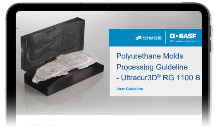
Full Guide: Polyurethane Molds with Ultracur3D® RG 1100 B / xPRO1100-Black
Share this page
In the rapidly evolving world of product development, speed and flexibility are a must. This is where 3D printed polyurethane (PU) molds step in, redefining the prototyping process with efficiency and innovation at its core. Through a collaborative effort between BASF Forward AM and Nexa3D, the Ultracur3D® RG 1100 B (rebranded as xPRO1100-Black by Nexa3D) material comes as a definitive solution, enabling the creation of PU molds that are not just quick to produce but also remarkably durable and precise.
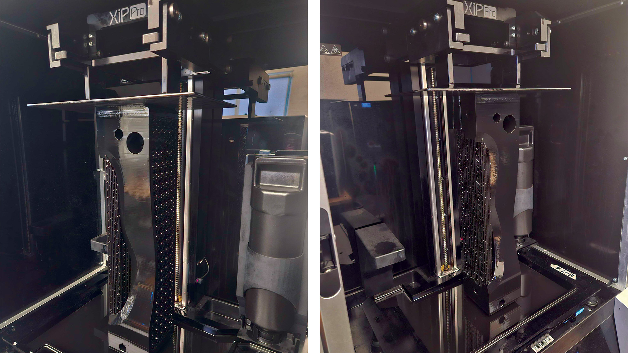
Polyurethane mold 3D printed on a Nexa3D XiP Pro with xPRO1100-Black resin powered by BASF Forward AM

A Sneak Peek into the Future of Prototyping
While the traditional way of CNC machining is reliable, it often becomes a bottleneck due to its time-consuming processes. On the other hand, the 3D printing of PU molds not only enables the rapid production of prototypes, but also helps to assess part design and functionality at an earlier stage. It allows companies to offer a broader variety of prototypes or even small series batches to potential customers for early feedback.
The Ultracur3D® RG 1100 B Advantage & Molding Excellence
Developed by BASF Forward AM, Ultracur3D® RG 1100 B is a rigid material with exceptional stiffness and temperature resistance. This high-strength polyurethane-based engineering grade resin shows mechanical properties comparable to widely spread injection molding grades used in automotive or other demanding industries.
Due to its high heat deflection temperature (HDT 100°C), excellent chemical resistance and long-term UV-stability, this material is perfectly suitable for applications such as automotive connectors, exacting engineering parts, exterior covers, brackets and housings.
Benefits at a Glance
- Very high stiffness
- Impressive all-round temperature resistance
- Very high chemical resistance and low water uptake
To begin utilizing 3D printed molds for polyurethane involves careful mold preparation must be undertaken. Our comprehensive User Guideline delves deep into the entire process of creating PU molds from design optimization and printing to post-processing and demolding. Each step is optimized through rigorous testing at BASF Polyurethanes GmbH in Lemförde, ensuring that you achieve precision and efficiency in every prototype.
Ideally this would be combined with expertise in design for additive manufacturing (DfAM), printing, post-processing, and finally in polyurethane injection or casting. When done correctly, this method can greatly shorten lead times and reduce costs during the early stages of any PU foaming project when compared to traditionally CNC-milled molds.
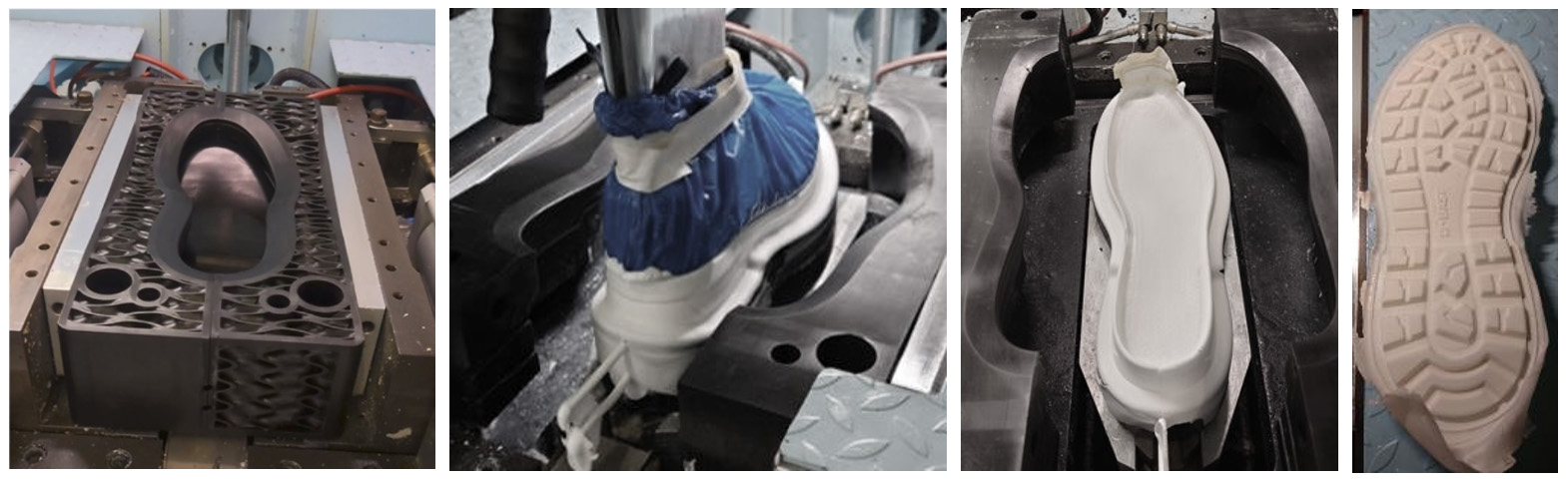
Molding trials were performed at BASF Polyurethanes GmbH on a round-table system using a standard DESMA mold design with a 300g/L PU-Foam. Fully solid printed molds as well as gyroid filled molds were tested with good results.
Moving your Molding Forward with Ultracur3D® RG 1100 B
In order to achieve best-in-class performance, the experts at Forward AM recommends the following key guidelines to ensure precision in every step, optimizing the additive manufacturing process for polyurethane molds. Testing was done during all steps of creating PU-foam parts: starting from machining of the printed parts, to demolding, cleaning and testing of different molds like casting, injection as well as round-table molds.
1) MOLD DESIGN OPTIMIZATION
In general, the design guidelines of PU molds should be applied, but with the consideration that thin features should be avoided as a mold made of a photopolymer printed material such as the Ultracur3D® RG 1100 B has lower strengths than aluminum or steel molds.
Employing an infill pattern can virtually eliminate warping during the printing process. For those new to Design for Additive Manufacturing (DfAM), Forward AM offers comprehensive consulting services that are designed to help you fully grasp the extensive design opportunities enabled by this technology as well as understand its limitations.
A few insights to keep in mind:
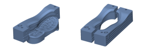
- Hollow the mold and fill it with infill to save up to 40% material and reduce warpage
- Explore BASF Forward AM’s DfAM Service to improve your mold design — contact us to start optimizing today
- Keep a >5mm wall inside the mold to resist process pressure
- Allow a tolerance of 0.5mm between sides and stamp to ensure smooth movement
2) PRINTING
To ensure the highest quality of edge sharpness at the parting line, position the molds either horizontally or vertically relative to the printing plate avoiding overhangs and undercuts. For optimal detail sharpness, a layer thickness of 50 to 70 microns is recommended, though thicknesses up to 100 microns can still be effective.
In the context of large geometries, such as those found in molds for polyurethane, it is essential to account for extended travel distances and increased waiting times for shifts. Ensuring a completely flat surface is also crucial, particularly at the parting line and on the mold’s back side. A failure to maintain these standards can result in stress fractures when the molds are clamped.
3) POST-PROCESSING
To achieve final mechanical properties and the necessary thermal resistance of the molds, post processing is required after printing. Heat treatment is optional but strongly recommended as it can increase heat resistance, resulting in higher durability and preventing the expected shrinkage under thermal stress during the process. The individual steps are illustrated below:

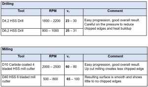
4) PROCESSABILITY AND MACHINABILITY
Shrinkage and warpage are common to all plastics processes, especially where part thickness is high. The same is true for 3D printing. As molds or mold inserts are used in a technical environment of precisely machined metal components, machining and reworking 3D printed molds is a good way to achieve tighter tolerances for proper fit and alignment.
For more details and news on PU soles please visit www.footwear.basf.com.
5) MOLDING PROCESS
Molding trials were performed on a round-table system using a standard DESMA mold design with a 300g/L PU-Foam. Fully solid printed molds as well as gyroid filled molds were also tested with good results. The demolding time of the systems were 4 and 6 minutes and PU foam soles with densities of 300-450 g/L were produced. During production of the soles, the molds were subjected to machine-induced closing forces up to 7.4 tons.
6) DEMOLDING
For demolding, Elastopan® PU systems offer high-performance and innovative solutions for producers of casual shoes, safety shoes, boots and sport shoes. These are tailor-made polyurethane foam systems to produce unit-, mid-, out- and insoles. It is compatible with casting and direct injection machines.
7) CLEANING
Bomix Cleaner 60/87, which is specifically formulated as a release agent, and Bomix Mold Cleaner 60/6107, designed for removing stuck foam parts in the mold, should be applied. The cleaner can be left on the surface of the inlay overnight with no issues effecting the surface.
For more information on this rigid material with exceptional stiffness and temperature resistance, check out our product page at: Ultracur3D® RG 1100 – BASF FORWARD AM (forward-am.com)